Multifunction Meters (MFM meters) are essential components in modern electrical systems, helping monitor various electrical parameters like voltage, current, power factor, and energy consumption. However, like all electronic devices, these meters can sometimes display incorrect readings or encounter operational faults. In this comprehensive guide, we will walk you through the most common MFM meter errors, explain the causes, and provide step-by-step energy meter troubleshooting tips.
Whether you’re an engineer, technician, or facility manager, this guide will help you quickly identify and resolve digital meter issues, especially when facing MFM meter display problems in the field.
Table of Contents
What is an MFM Meter?
An MFM (Multifunction Meter) is a digital instrument used to measure multiple electrical parameters in 3-phase systems. These parameters often include:
- Line-to-line and line-to-neutral voltage
- Current per phase
- Frequency
- Active, reactive, and apparent power
- Energy (kWh, kVARh)
- Power Factor
Because of their critical role in power monitoring and energy management, ensuring their accuracy and proper function is vital.
Common MFM Meter Errors and What They Mean
Understanding the errors is the first step in energy meter troubleshooting. Below are the most frequently observed MFM meter errors and what they typically signify:
1. Negative Active Power Readings
- Possible Cause: Reverse CT polarity or wrong CT wiring.
- Fix: Swap S1 and S2 of the CT or correct the phase sequence.
2. Incorrect Voltage Readings
- Possible Cause: Loose terminals, blown fuse, or wrong wiring.
- Fix: Tighten connections, check phase sequence, and inspect protection fuses.
3. Power Factor Reading in Negative
- Possible Cause: Load connected in reverse or CT orientation error.
- Fix: Reverse CT wiring or change configuration in meter setup menu.
4. MFM Meter Display Problem (Blank or Flickering)
- Possible Cause: Power supply issue or internal display failure.
- Fix: Check auxiliary power supply (typically 230V AC or 110V DC), and inspect for internal circuit damage.
5. Wrong kWh Readings
- Possible Cause: Incorrect CT ratio or wiring.
- Fix: Verify CT rating and compare with meter settings.
Step-by-Step Troubleshooting Guide for MFM Meters
Step 1: Visual Inspection
Start with a simple visual inspection:
- Check if the display is ON.
- Ensure all terminals are tightly connected.
- Look for burnt marks, broken seals, or signs of overheating.
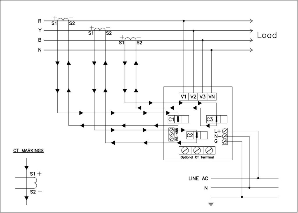
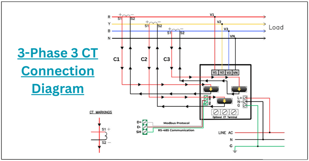
Step 2: Check CT and PT Connections
MFM meters often rely on CTs (Current Transformers) and PTs (Potential Transformers). Ensure:
- CT polarities (S1, S2) are correct.
- CT secondary is not open-circuited.
- PT fuses are not blown.
- PTs are connected according to the meter’s required wiring diagram (e.g., 3P3W or 3P4W).
Step 3: Verify Voltage Inputs
Using a multimeter:
- Measure the input voltage at each terminal.
- Confirm the voltage matches the rated supply.
- In 3-phase 4-wire systems, check voltage between L1-N, L2-N, L3-N, and L1-L2-L3.
Step 4: Check Phase Sequence
Wrong phase sequence can cause errors in power and energy readings.
- Use a phase sequence meter to confirm.
- Correct the sequence if needed.
Step 5: Confirm CT Ratio Configuration
Mismatched CT ratios lead to wrong kW and kWh readings.
- Example: If your CT is 100/5A but the meter is set to 200/5A, it will under-read by 50%.
- Always match the CT ratio in settings with the physical CTs installed.
Step 6: Review Meter Programming Settings
Navigate through the meter settings using front panel buttons:
- CT/PT ratios
- Demand settings
- Wiring configuration (3P3W or 3P4W)
- Communication protocol settings (if using MODBUS/RS485)
Step 7: Compare Meter Readings with Clamp Meter
Take real-time readings using a calibrated clamp meter:
- Compare current and voltage readings.
- Check if there’s a mismatch beyond tolerance (usually ±1%).
Real-World Example: Negative Power Factor Issue
A technician was called to a site where the MFM meter power factor showed -0.997 during inverter operation. Here’s how the issue was resolved:
- Observation: Negative power factor and reactive power.
- Troubleshooting:
- Checked inverter output wiring – found no issues.
- CT wiring was reversed (S1 and S2 interchanged).
- Action: Reversed CT polarity.
- Result: Power factor normalized to +0.998, reactive power values accurate.
This is a classic MFM meter error caused by incorrect CT installation, a frequent issue in solar and DG setups.
MFM Meter Display Problem: Blank Screen or No Data
Sometimes the MFM meter display stops working or shows erratic flickering:
Possible Reasons:
- Loss of auxiliary supply (common in panel faults)
- Internal damage from surges
- Loose connection on terminal block
Solution:
- Measure supply voltage at the meter terminal (typically A1 & A2).
- If voltage is okay, remove and inspect the meter.
- In some cases, internal fuse may blow — replace only if trained and authorized.
Regular Maintenance Tips
To avoid recurring digital meter issues, follow these maintenance best practices:
- ✔️ Tighten terminals every 6 months.
- ✔️ Periodically verify CT/PT ratios and wiring.
- ✔️ Calibrate the meter once every 1–2 years.
- ✔️ Keep MODBUS/RS485 terminals shielded and terminated properly.
Pro Tips for Installation and Setup
- Always refer to the manufacturer’s wiring diagram.
- Use CTs with burden not exceeding the meter’s rated input.
- If using MODBUS, match parity, baud rate, and stop bits in all devices.
Conclusion
MFM meter errors can range from simple wiring mistakes to serious electrical faults. By following this step-by-step energy meter troubleshooting guide, you can resolve common digital meter issues such as negative power values, wrong readings, or MFM meter display problems.
As electrical systems grow more complex, the need for accurate metering and proactive troubleshooting becomes even more critical. Always keep safety in mind, and if you’re ever in doubt, consult with a certified technician or the manufacturer.
FAQs: Troubleshooting MFM Meter Errors
Why is my MFM meter showing negative active power?
A negative active power reading typically indicates reverse current flow, often due to incorrect CT polarity or phase wiring. Ensure the CT direction (P1 and P2) and phase connections (R-Y-B) are properly aligned with the load direction.
How do I fix low voltage readings in my MFM meter?
Low voltage readings may result from loose voltage terminal connections, wrong PT ratios, or incorrect voltage phase wiring. Verify all voltage inputs are properly connected and match the configured PT ratio.
What causes the MFM meter to display negative reactive power?
Negative reactive power often means the system is exporting reactive power. This can happen when capacitor banks are overcompensating or when using grid-tied inverters. Check the power factor correction setup and CT alignment.
Why is the MFM meter not showing any current values?
If current readings are missing, check if:
CT secondary wiring is disconnected
CTs are open-circuited
Meter configuration does not match CT ratio
Always ensure CT terminals are properly tightened and the CT ratio is set correctly in the meter.
How can I correct wrong energy (kWh) readings on my MFM meter?
Incorrect energy readings may stem from:
Wrong CT/PT ratios
Incorrect phase sequence
Unbalanced loads
Recheck the meter configuration, especially CT/PT ratios and the wiring scheme.
What does “Phase Failure” mean on an MFM meter?
“Phase Failure” indicates that one or more voltage phases (R, Y, or B) are missing or improperly connected. Inspect the voltage input terminals and ensure a 3-phase supply is present and correctly wired.
Why is my MFM meter not communicating over MODBUS?
Check for these issues:
Incorrect slave ID
Wrong baud rate or parity settings
Loose or reversed RS-485 A/B wires
Also, ensure that termination resistors are installed if required, and that the device is properly grounded.
How do I resolve inaccurate power factor readings in my MFM meter?
Inaccurate PF readings usually point to:
CT polarity errors
Phase shift in wiring
Overcompensation by capacitors
Recheck CT orientation, wiring phase sequence, and any reactive compensation devices.
What should I do if my MFM meter resets frequently?
Frequent resets could be due to:
Power supply instability
Faulty internal power circuitry
Electromagnetic interference (EMI)
Ensure a stable auxiliary power supply and proper EMI shielding in industrial environments.
How to check if CT polarity is correct in an MFM meter?
Incorrect CT polarity can result in negative power readings. To verify:
Use the meter’s test mode if available
Compare the actual power direction (import/export) with readings
Ensure P1 faces the source and P2 faces the load