Understanding the 3 Phase Energy Meter with CT
In industrial and commercial electrical installations, monitoring power consumption accurately is crucial. One of the most common setups used for this purpose is the 3 Phase Energy Meter with CT (Current Transformer). This configuration is ideal for systems with high current loads, where direct connection to the energy meter is not feasible due to safety and equipment limitations.
This guide provides a detailed explanation of the wiring diagram for a 3 phase energy meter with CT, targeted at both electrical engineering professionals and beginners. Whether you’re installing a new metering system or trying to troubleshoot an existing one, understanding this setup is essential for energy management, billing, and system protection.
Table of Contents
What is a 3 Phase Energy Meter with CT?
A 3 Phase Energy Meter is used to measure the power usage in a three-phase electrical system, commonly found in commercial and industrial buildings. When the current load is too high (typically over 100A), CTs (Current Transformers) are used to scale down the current to a safer, measurable range (usually 1A or 5A), which the meter can then read.
Key Components Involved:
- Three-Phase Energy Meter (Class 1.0/0.5S)
- Current Transformers (CTs) – Usually 3 units for R, Y, B phases
- Three-Phase Power Supply (R, Y, B & Neutral)
- Load (motors, panels, etc.)
- Protective Devices – MCBs, fuses, etc.
Why Use CTs with 3 Phase Energy Meters?
- Safety: Reduces high current to a manageable level
- Accuracy: Maintains accurate readings even for high loads
- Scalability: Can be used with large machinery and panels
- Meter Compatibility: Most energy meters are designed to work with 1A or 5A secondary inputs from CTs
Wiring Diagram for 3 Phase Energy Meter with CT
Below is a step-by-step breakdown of how to wire a 3 Phase Energy Meter using CTs. The wiring diagram can be represented in both schematic and tabular formats for clarity.
Basic Wiring Overview:
Assumptions:
- Meter Type: 3 Phase 4 Wire CT Operated (5A)
- CT Ratio: 300/5A
- Load: Industrial Motor Control Panel
- Power Supply: 415V AC (R, Y, B, N)
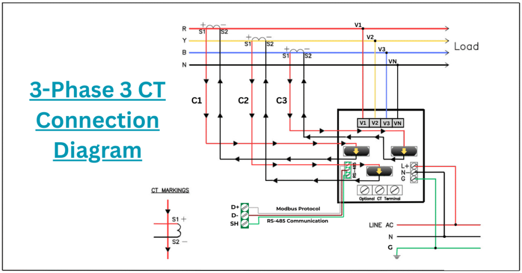
Wiring Connections – Step-by-Step
✅ Step 1: CT Placement on Incoming Lines
Install the 3 CTs on the incoming R, Y, and B phase lines that go to the load.
Ensure correct polarity marking – P1 (source side), P2 (load side).
✅ Step 2: Connect CT Secondary to Energy Meter
- Each CT has two secondary terminals: S1 and S2.
- Connect the S1 terminal of each CT to the respective current input terminal on the meter:
- R Phase CT S1 → Meter I1 (or L1)
- Y Phase CT S1 → Meter I2 (or L2)
- B Phase CT S1 → Meter I3 (or L3)
- Connect all S2 terminals together and route them to the common neutral current terminal on the meter or connect each S2 to the respective return current input as per meter model.
⚠️ Important: Always short the S1 and S2 of the CTs when not connected to a load/meter to prevent high voltage buildup.
✅ Step 3: Connect Voltage Inputs to Energy Meter
Connect the 3-phase supply lines directly to the meter’s voltage input terminals:
- R Phase → Meter V1
- Y Phase → Meter V2
- B Phase → Meter V3
- Neutral → Meter N
✅ Step 4: Grounding and Safety
- Ground the meter body using standard earthing methods.
- Install fuses or MCBs on the voltage input lines for protection.
Sample Wiring Diagram:

Real-World Example: Panel Installation
Imagine a 600A Industrial Panel at a manufacturing plant. You cannot feed this load directly into a standard energy meter.
- CTs with 600/5A ratio are installed on R, Y, B input cables.
- Secondary 5A outputs of CTs go to the 3 Phase Energy Meter.
- Meter is configured with CT Ratio = 600 (Primary) / 5 (Secondary)
- The final energy readings are scaled using this ratio for billing or analysis.
Tips for Accurate Meter Connection
To ensure safety, accuracy, and long-term reliability, follow these essential tips:
✅ 1. Correct CT Polarity
CTs have marked terminals: P1, P2, S1, S2
Always ensure:
- P1 faces the incoming source
- P2 faces the load side
- S1 connects to the energy meter input
- S2 goes to common return or neutral
✅ 2. Short CTs Before Disconnection
CTs generate high voltage if left open-circuited.
Always short the S1-S2 terminals when the meter is disconnected.
✅ 3. Match CT Ratio in Meter Settings
Configure the correct CT Primary and Secondary values in the meter to reflect accurate readings.
✅ 4. Use Proper Cable Size and Protection
Use shielded cables for CT secondary wires to avoid noise.
Protect voltage lines with fuses or miniature circuit breakers.
✅ 5. Verify Connections Before Power On
- Double-check all voltage and current wiring.
- Use a multimeter to test continuity and phasing.
Troubleshooting Common Issues
- Wrong Readings? → Check CT polarity and wiring
- No Reading? → CT secondary might be open
- Negative Power? → CT installed in reverse or phase mismatch
- Meter Not Powering On? → Check voltage connections and fuses
Conclusion: Wiring a 3 Phase Energy Meter with CT the Right Way
The 3 Phase Energy Meter with CT setup is essential for high-load energy measurement. Proper wiring, CT orientation, and meter configuration are the keys to accurate power monitoring. Whether you’re an electrical engineer or a technician, understanding this setup helps ensure energy audits, load analysis, and billing processes are precise and compliant.
By following this step-by-step guide and using the provided wiring diagram, you can confidently wire a 3-phase energy meter using CTs and ensure both operational efficiency and safety.