(A Complete Beginner-Friendly Guide)
Multifunction meters (MFM meters) are widely used in electrical panels to measure voltage, current, energy, frequency, power factor, demand, and various power parameters. For accurate measurements, the 3-Phase 3 CT Connection and PT Connection must be correctly connected.
Understanding the 3-Phase 3 CT Connection is vital for professionals working in electrical engineering.
Incorrect CT/PT wiring is the primary reason for wrong readings, negative power, wrong PF, or mismatched energy values in the field.
Before working with the 3-Phase 3 CT Connection, ensure you have the right tools and knowledge about wiring setups.
The 3-Phase 3 CT Connection helps in achieving precise measurements in various electrical applications.
This article explains step-by-step 3-Phase 3 CT Connection wiring, including the essential 3-Phase 3 CT Connection polarity rules, diagrams, mistakes to avoid, and methods to test your wiring before powering ON. Understanding the 3-Phase 3 CT Connection is crucial for accurate measurements and safe operation.
Why CT and PT Are Used with MFM Meters
CT (Current Transformer)
- Steps down high current (ex: 200A → 5A or 1A)
- Allows safe measurement
- Provides isolation
- Required in industrial panels
PT (Potential Transformer)
- Steps down high voltage (ex: 11kV → 110V)
- Used in high-voltage systems
For LT Panels (up to 440V) — PT is usually NOT needed.
For HT Panels (6.6kV, 11kV, 33kV) — PT is mandatory.
CT Wiring Basics for 3-Phase Systems (Very Important)
A CT has two terminals on primary and two terminals on secondary.
Primary – P1 and P2
In high-voltage systems, the 3-Phase 3 CT Connection plays a crucial role in safety and accuracy.
Secondary – S1 and S2
- P1 → Supply side (incoming)
- P2 → Load side (outgoing)
Secondary polarity
- S1 = Positive
- S2 = Negative
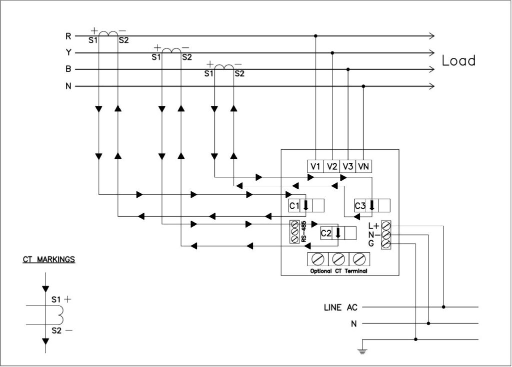
CT Wiring Diagram for 3-Phase 3 CT Connection (Simple)
")
3-Phase 3 CT Connection
You must connect:
- 3CTs (R, Y, B)
- 3 Phase voltages (R, Y, B)
- Neutral (N)
Polarity Rules in 3-Phase 3 CT Connection
S1 must always go to meter’s I+ terminal.
S2 must go to meter’s I– terminal.
If polarity reverses, you get:
🚫 Negative power
🚫 Wrong PF (leading/lagging mismatch)
🚫 Energy mismatch
🚫 Wrong current direction on SCADA
PT Wiring (Only for HT Panels)
Standard PT secondary:
- 110V (for 11kV, 33kV systems)
- 3-phase, 3-wire OR 3-phase, 4-wire
PT Terminals:
- V1 – R phase
- V2 – Y phase
- V3 – B phase
- VN – Neutral (if available)
System Selection in Meter (Critical)
Proper setup of the 3-Phase 3 CT Connection can prevent common electrical issues.
Inside the MFM meter settings:
It is essential to refer to the 3-Phase 3 CT Connection wiring diagram for clarity.
Select the correct system:
For best practices, always double-check your 3-Phase 3 CT Connection before powering any equipment.
- 3P4W (most common in LT panels)
- 3P3W
- 1P2W
- 1P3W

Select CT Ratio:
Example:
If CT is 200/5A → set CT Primary = 200A, Secondary = 5A.
Select PT Ratio:
Example:
11kV/110V → set PT Primary = 11000V, Secondary = 110V.
Common CT Wiring Mistakes (Field Experience)
1. Reversing S1 and S2
– Produces negative power.
2. Forgetting to short S2 terminals
– Causes floating reference → wrong reading.
3. Keeping CT secondary open
⚠ Very dangerous — can damage CT.
Understanding the nuances of the 3-Phase 3 CT Connection can enhance your troubleshooting skills.
4. CT installed in reverse direction
– P1 towards load → wrong PF and power.
5. Wrong CT ratio entered in meter
– Energy mismatch.
6. Mixed CT phases (CT2 connected to CT3 terminal)
– Totally wrong readings.
How to Test CT Wiring Before Power ON
Step 1 – Check polarity
Use a multimeter in continuity mode:
- Touch S1 → should show continuity to meter I+
- Touch S2 → should show continuity to meter I–
Step 2 – Load Test
Put a clamp meter on each phase:
Example:
If clamp shows 50A and meter shows 50A, CT wiring is OK.
Step 3 – PF Consistency
- Inductive loads (motors): PF should be lagging
- Capacitor banks: PF should be leading
If meter shows reverse → CT polarity wrong.
Frequently Asked Questions (FAQs)
Can I connect only 2 CTs in a 3-phase meter?
Yes, for 3P3W systems (open-delta), 2 CTs are used.
What happens if CT secondary is open?
Dangerous — high voltage can appear, CT may burn.
What CT ratio should I use?
Mastering the 3-Phase 3 CT Connection is essential for electrical efficiency.
CT primary = Panel incoming current
CT secondary = 5A or 1A depending on meter type.
Do LT panels require PT?
No, LT (440V) directly connects to meter voltage terminals.
Meter showing wrong PF. Why?
Most likely CT polarity reversed.
Final Summary
Correct CT/PT wiring is essential for accurate MFM meter readings. Always follow:
- P1 → Source
- P2 → Load
- S1 → Meter I+
- S2 → Meter I–
- S2 terminals must be shorted
- Set correct CT/PT ratio
- Select correct system (3P4W / 3P3W)
When done correctly, the meter will show accurate:
- Current
- Voltage
- Power
- PF
- Energy
- Demand
- Load profile
In summary, the 3-Phase 3 CT Connection is critical for accurate readings and should be handled with care.
With the right approach, mastering the 3-Phase 3 CT Connection will ensure quality performance in your electrical systems.
Achieving expertise in the 3-Phase 3 CT Connection leads to improved efficiency in electrical measurements.
The 3-Phase 3 CT Connection is not just a technical requirement; it is foundational for any electrical engineer.
More Topics: MFM Meter Errors: Troubleshooting Guide for Common Digital Energy Meter Issues-2025